What You Are Learning
By the end of this lesson, you will understand what a splice is, why fiber networks cannot be built without splices, and where splices live once they are made. You will know the difference between the two main ways of making a splice, fusion and mechanical, at an overview level. You will know what a splice closure is and why every splice needs protection. You will also know how to recognize splice locations in the field from the surface.
You will not be qualified to make a splice. Splicing is trained crew work that involves bare glass fiber, sharp cleaved ends, and specialized equipment. Recognition is your job. The splicing itself belongs to qualified splicers, and the detailed technique is covered much later in this library, in Level 19.
Start With the Basics
Picture a garden hose that is too short to reach the far end of a yard. You have two choices. You can buy one very long hose, or you can join two shorter hoses together so they act as one. Fiber cable has the same problem, only bigger.
A fiber route can run for miles. Cable is manufactured and shipped on reels, and a reel holds only so much cable. Crews can also only pull so much cable through conduit in one pull before friction and pulling tension become a problem. So a long route is built from several cable lengths, and where one length ends and the next begins, the individual glass fibers inside have to be joined, fiber by fiber, so light can travel straight through as if the cable had never been cut.
That join is a splice. Everything else in this lesson follows from that one idea: a splice is where two fibers become one continuous path for light.
There are other reasons for splices too. A branch cable has to connect to a main cable somewhere. A cable cut by a digging accident has to be repaired. A cable entering a building or a cabinet often has to connect to a different, smaller cable inside. Each of those moments is a splice point, planned or unplanned.
What Is It?
A splice is a permanent or semi-permanent join between two optical fibers, made so that light passes from one fiber into the other with as little loss as possible. To understand that definition, you need three smaller ideas first.
An optical fiber is a thin strand of glass that carries light signals. The light travels in the center of the strand, called the core. If two fibers are to act as one, their cores have to line up almost perfectly, because the core is tiny and even a small offset lets light escape at the joint.
Splice loss is the amount of light that does not make it across a joint. Every splice loses a little light. A good splice loses very little. A poor splice loses more, and enough loss added up across many splices can weaken a signal before it reaches its destination. How much loss is acceptable on a given job is set by the design and the contract specifications for that project. There is no single universal number that applies to every network, and this lesson does not give you one. When you hear a typical figure, treat it as a description of what good work usually achieves, not as a pass or fail rule.
A splice is not a connector. A connector is a plug that can be connected and disconnected by hand, the way you unplug a cable from a wall jack. A splice is meant to stay joined. That permanence is why splices are used out on the route, where joints need to survive for years without anyone touching them, while connectors are used where people need to rearrange connections, such as inside buildings and cabinets.
There are two main ways to make a splice, and this lesson covers both only at overview level:
- Fusion splicing. The two fiber ends are cleaned, precisely cut, aligned in a machine called a fusion splicer, and melted together with an electric arc so the glass itself joins into one piece. The Fiber Optic Association (FOA) describes fusion splicing as the most widely used method, providing the lowest loss and the strongest, most reliable joint. Most outside plant splicing is fusion splicing.
- Mechanical splicing. The two fiber ends are cleaned and precisely cut, then held facing each other inside a small alignment device that keeps their cores lined up without melting the glass. The fibers are held, not welded. Mechanical splices generally have higher loss than fusion splices, and industry sources describe them as most useful for quick or temporary restoration and for situations where fusion equipment is not available. Permanent outside plant work is normally fusion spliced, but what a specific project allows is decided by its specifications.
In both methods, the bare joined fiber is fragile. A splice is never left naked. It gets a protective sleeve and then a protected home, which the next sections explain.
What Does It Look Like?
You will almost never see an actual splice outdoors, because a finished splice is sealed inside protective hardware. What you can learn to recognize is the hardware that tells you splices are there.
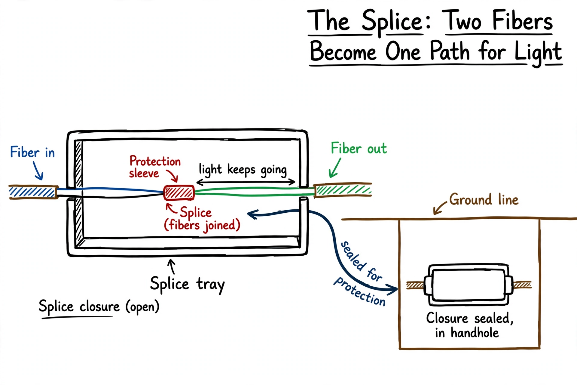
Start with the smallest piece. A single fusion splice, right after it is made, looks like a short section of bare glass fiber with a small clear tube shrunk over the joint. That tube is a splice protection sleeve. It is a heat shrink sleeve that the splicer slides over the joint and heats so it shrinks tight around the fiber. Inside the sleeve is a thin steel strength rod that keeps the joint straight and stops it from bending at its weakest point. The sleeve protects the bare glass, which at the joint has no coating and would snap easily without support.
Splices are then laid into a splice tray. A splice tray is a flat, shallow organizer, usually plastic, that holds a set of splices in neat loops and slots. The tray keeps each spliced fiber gently coiled, holds the protection sleeves in fixed positions, and keeps fibers identified and separated so a future crew can find a specific one. Trays stack on top of each other inside the larger case.
That larger case is the splice closure. A splice closure is a sealed protective enclosure, commonly a cylindrical dome shape or a flatter rectangular box, made of tough plastic. Cables enter and leave through sealed ports in the closure. Inside are the stacked splice trays. The closure is the weatherproof and crush resistant home for the splices, and it is built so qualified crews can reopen it later, do work, and seal it again.
Where you will see closures in the field:
- Inside a handhole (Lesson 5), resting in or mounted in the box alongside slack coils.
- On a utility pole or strand, as a dark cylindrical or box shaped case mounted up on the pole or hanging from the aerial cable.
- Inside a cabinet or similar enclosure at the edge of a neighborhood or at a building, where the outside cable connects to distribution cables.
- In a splicing trailer or van during construction. Because splicing needs a clean, controlled space, crews often pull slack cable up into a trailer or van, make the splices there on a workbench, then place the sealed closure back into the handhole or onto the pole.
So the field picture is this: you do not look for the splice itself. You look for the closure, and you know that a closure on a route means fibers are joined inside it.
What Does It Do?
A splice does one job: it makes two fibers act as one continuous fiber, so the light signal crosses the joint and keeps going.
That simple job is what makes long networks possible. Without splices, a fiber route could be no longer than a single reel of cable that a crew could pull in one piece. With splices, crews can:
- Join cable lengths end to end to build routes far longer than one reel.
- Connect a branch cable to a main cable, so one route can serve side streets, buildings, or neighborhoods along the way. The FOA notes that outside plant cables are commonly spliced for exactly these reasons, including dropping cables at locations and splitting a cable out into different fiber connections.
- Repair a damaged or cut cable by cutting out the damaged section and splicing in a new piece of cable, which usually means two splice points, one at each end of the repair piece.
- Transition between cable types, for example where a large outside plant cable meets smaller cables that fan out to individual locations, or where an outdoor cable connects to indoor rated cable at a building entrance.
In each case, the splice itself is invisible in daily operation. The network simply works as if the cable were continuous, as long as each splice was made cleanly and protected properly.
Where Does It Fit?
Splicing happens after the pathway and cable are in place. The sequence on a typical build goes like this: the pathway is built (Lesson 3), conduit is placed (Lesson 4), handholes and other structures are set (Lesson 5), cable is pulled or blown through the pathway and slack is left at splice locations, and then the splicing crew makes the joins and seals them in closures.
That order matters for a beginner to understand. Splice locations are not random. The design decides in advance where cables will be joined, and crews leave extra cable, the slack you learned about in the handhole lesson, at those locations so the splicer has enough cable to work with. Splicing cannot fix a route where no slack was left or where the closure has no structure to live in.
Splicing also fits into the life of the network long after construction. Restoration crews splice when a cable is cut. Maintenance and upgrade work can require opening a closure, changing which fibers connect where, and resealing it. Testing crews check splice quality with instruments after splicing, and the results become part of the project records. A later level covers testing in detail. For now, hold this picture: design plans the splice points, construction crews build to them, splicers make the joins, testers verify them, and the closure protects them for the life of the network.
Why Does It Matter?
Splices matter for three practical reasons.
First, they are unavoidable. Cable comes on reels of limited length, pulls have practical limits, branches have to connect, and cables get damaged. Every real network has many splice points. A network design is, in part, a plan for where splices will be and how they will be protected.
Second, splice quality affects the whole link. Each splice adds a small amount of loss. One good splice is barely noticeable to the signal. Many poor splices along a long route add up, and a single badly made splice can become the weak point that limits the entire connection or fails later. This is why splicing is skilled work with testing behind it, not a quick field fix anyone can do.
Third, a splice is only as good as its protection. The joined glass at a splice is the most fragile point in the cable. Left unprotected, it can break from bending, vibration, water, or simple handling years later. The protection sleeve, the tray, and the sealed closure are not packaging. They are what turn a delicate glass joint into something that can survive underground or on a pole for the life of the network. A well made splice in a poorly sealed closure is still a future failure.
What Does Good Look Like?
Good at a splice location, in general good practice terms, looks like this:
- The splices themselves were made by a qualified splicer using a fusion splicer, with clean, well cleaved fiber ends, and the results were tested as the project requires. Testing results are recorded, not assumed.
- Every splice has its protection sleeve properly shrunk over the joint, with the joint centered in the sleeve.
- Splices sit neatly in a splice tray, sleeves held in their slots, fibers coiled in smooth loops with no tight bends, kinks, or fibers pinched under tray covers.
- The closure is sealed the way its manufacturer instructs, with cable entry ports sealed so water and dirt cannot get in.
- The closure is placed or mounted securely where it belongs, in the handhole, on the pole, or in the cabinet, with slack cable stored neatly alongside it so a future crew can pull it out and work on it.
- Records match reality: the splice location, which fibers connect to which, and test results are documented so the next crew is not guessing.
One distinction matters here, the same one you met in earlier lessons. The list above describes general good practice in the industry. Whether a specific splice or closure is accepted on your project is decided by the contract specifications, the owner’s requirements, and the manufacturer’s instructions for the products used. Some projects specify fusion splicing only. Some set their own loss limits for test results. “Good” on your project means what its documents say, checked the way its documents require.
A note on typical loss figures, so you hear them correctly. Industry writing commonly describes fusion splices as having very low loss. For example, a Cabling Installation and Maintenance article on fusion splicing describes typical fusion splice loss as less than 0.02 dB. Treat numbers like that as typical performance reported by a source, not as your project’s acceptance limit. Acceptance limits come from the project documents and are verified with test equipment by qualified testers.
What Can Go Wrong?
Problems at splices fall into two groups: problems with the joint itself, and problems with its protection.
Problems with the joint:
- Dirty or poorly cleaved fiber ends. Splicing starts by stripping the coating off the fiber and cleaving it, which means scoring and snapping the glass to get a flat, square end. Dirt on the fiber or a rough, angled cleave makes the cores line up badly, and the splice loses more light or fails outright. This is why splicing is done in a clean, sheltered workspace whenever possible.
- Misalignment. If the cores do not line up, light escapes at the joint. Modern fusion splicers align fibers automatically and estimate the loss of each splice, and a splicer who sees a bad estimate remakes the splice. A splice that was never checked cannot be trusted.
- Wrong fibers joined. A cable can contain many fibers, identified by color coding. Joining the wrong pair does not break the glass, but it breaks the design: the signal arrives at the wrong place, and troubleshooting that mistake later takes time.
Problems with protection:
- Missing or badly fitted protection sleeve. Without the sleeve and its strength rod, the bare joint can bend and snap during handling or later in the tray.
- Poorly organized tray. Fibers forced into tight bends, pinched by the tray lid, or left in a tangle can lose light at bends or break when the next crew opens the closure.
- Unsealed or damaged closure. Water entering a closure degrades the contents over time and can freeze in cold weather. A closure crushed in a handhole or knocked loose on a pole exposes every splice inside it.
- No slack at the closure. If a crew later needs to repair or remake a splice and there is no spare cable to pull into the work area, a small repair can turn into a cable replacement.
Notice the pattern: almost all of these are workmanship and protection problems, not mysteries. They are prevented by trained splicers, clean working conditions, correct materials, and testing, and they are exactly what inspectors and records are meant to catch.
What Should Someone Notice in the Field?
A beginner’s job at a splice location is to notice the outside of things, not to open anything. Here is what you can usefully observe:
- Closure locations. Learn to spot splice closures: the dome or box shaped case in a handhole, mounted on a pole, or inside a street side cabinet. When you see one, you know fibers are joined there, and that location is a splice point in the network design.
- Closure condition from the outside. A closure that is cracked, hanging loose from a pole mount, sitting in standing water in a handhole, or buried under debris is worth photographing and reporting through your project’s normal process. You are reporting the condition of the protection, which is a real and useful observation.
- Slack at splice points. Notice whether spare cable is coiled neatly at the closure location. Neat stored slack means a future crew can work there. Missing slack or a closure jammed in with no working room is worth noting.
- Splicing work in progress. You may see a splicing trailer or van parked at a handhole or pole, with cable running from the structure up into the vehicle. That setup is normal: it gives the splicer a clean, sheltered bench. Notice it, give the crew room, and do not treat the work area as a walkway.
Safety, stated plainly:
- Never look into the end of a fiber or a connector to check whether it is live. Fiber signals are light, often infrared and invisible, and looking into a live fiber can damage your eyes. Qualified technicians check with instruments, never with their eyes. Treat every fiber as if it is carrying light.
- Splicing involves cleaved glass. The small pieces of glass cut off during splicing are sharp, nearly invisible shards that can get into skin and eyes. Splicers work with eye protection, keep a clean bench, and dispose of fiber scraps in proper containers. A beginner does not handle bare fiber or fiber scraps, ever.
- A fusion splicer works with an electric arc, and splicing also involves chemicals and cleaning solvents in trained hands. This equipment belongs to trained crews. Reading this lesson does not qualify you to strip, cleave, or splice a fiber, to open a splice closure, or to handle splicing tools.
- Your safe and useful role is recognition: know a splice point when you see its closure, notice damage or poor condition from the outside, and report it. Leave the glass to the people trained to work with it.
Practical Example
This is a hypothetical example, not a report of a real incident.
A hypothetical new subdivision build has a main fiber route running down its entrance street, with branch cables feeding three side streets. The design places a splice closure in a handhole at the entrance, where the branch cables join the main cable, and more closures along the main route where cable reels end and the next length begins.
The pathway crew finishes, the cable crew pulls cable and leaves tidy slack coils at each planned splice location, and the splicing crew works from a trailer parked at the entrance handhole. Over two days they fusion splice the branch connections and the reel to reel joins, lay each splice in its tray, seal the closures, and test every splice as the project specifications require. The closures go back into the handholes, lids go on at grade, and the records show every splice point and test result.
Six months later, a hypothetical landscaping crew cuts a branch cable on one side street. Because the records show exactly where the splices and slack are, the repair crew opens the entrance closure location, pulls the stored slack into their trailer, cuts out the damaged section, splices in a repair piece at two new splice points, tests the repair, and reseals the closure. Service is restored the same day, and no other street is disturbed.
The beginner’s lesson in this story is how much of that smooth repair was decided before anything went wrong: splice points were planned, slack was left, closures were sealed, and records were kept. The splice itself took minutes. Everything around it is what made it work.
Key Terms
- Splice. A permanent or semi permanent join between two optical fibers so light passes from one into the other as a continuous path. The subject of this lesson.
- Fusion splicing. Joining two fibers by aligning them in a fusion splicer and melting the glass ends together with an electric arc. The most widely used method in outside plant work, with the lowest loss and the strongest joint.
- Mechanical splicing. Joining two fibers by holding their ends precisely aligned inside a small device, without melting the glass. Generally higher loss than fusion, and most often used for quick or temporary restoration.
- Fusion splicer. The machine that aligns two prepared fiber ends and fuses them with an electric arc. It also estimates the loss of each splice it makes. Operated only by trained splicers.
- Cleave. The precise cut made across a fiber to produce a flat, square end before splicing. Splice quality depends heavily on cleave quality. The cut off pieces are sharp glass shards and a safety hazard.
- Splice loss. The amount of light that fails to cross a splice joint. Every splice has some. Acceptable limits on a job come from the project design and contract specifications, not from a universal number.
- Splice protection sleeve. A small heat shrink tube with a steel strength rod inside, shrunk over a finished splice to protect the bare glass joint and keep it straight.
- Splice tray. A flat organizer that holds finished splices in neat loops and slots, keeping fibers separated, identified, and protected from tight bends. Trays stack inside a splice closure.
- Splice closure. The sealed protective case that holds splice trays and spliced fibers where cables are joined. Found in handholes, on poles, and in cabinets. Opened only by qualified crews.
- Connector. A reusable plug on a fiber end that can be connected and disconnected by hand. Different from a splice, which is meant to stay joined.
- Slack. (From Lesson 5.) Extra cable left intentionally in a coil at splice locations so splicers have cable to work with and future repairs are possible.
Check Your Understanding
1. A fiber route is longer than one reel of cable and longer than a crew can pull in one piece. How does the route get built anyway? 2. What is the basic difference between a fusion splice and a mechanical splice? 3. You are walking a route and see a dark cylindrical case mounted on a pole, with cables entering its sealed ports. What is it, and what does its presence tell you? 4. A splice is tested and shows more loss than the project allows. Whose documents decide what happens next, and why is there no universal number you could have memorized instead? 5. Why is a finished splice never left bare, and what two layers of protection does it get before the closure is sealed?
Answer key
1. The route is built from several cable lengths joined by splices. Where one length ends and the next begins, the fibers are spliced inside a splice closure, so light travels the whole route as if the cable were continuous. 2. A fusion splice melts the two glass fiber ends together with an electric arc in a fusion splicer, making the fibers one piece of glass. A mechanical splice holds the two ends aligned inside a small device without melting them. Fusion is the standard for permanent outside plant work and has the lowest loss; mechanical is generally higher loss and is most often used for quick or temporary restoration. 3. It is a splice closure. Its presence tells you that fibers are joined at that point in the network, protected inside on splice trays, and that the location is a planned or repair splice point. 4. The project contract specifications and the owner’s requirements, along with the manufacturer’s instructions for the products used, decide acceptance and what happens next. Splice loss limits depend on the network design and its overall loss budget, so no single universal pass or fail number applies to every job. 5. Because the glass at the joint is bare and fragile and would bend or snap without support. It first gets a splice protection sleeve shrunk over the joint, with a steel rod keeping it straight, and then it is laid into a splice tray inside a sealed splice closure that protects it from water, dirt, and crushing.
Lesson Takeaway
A splice is where two fibers become one continuous path for light. Splices exist because cable comes in limited lengths, routes branch, cables get cut, and cable types change. Fusion splicing, which melts the glass ends together, is the standard method for permanent outside plant work; mechanical splicing holds ends aligned without melting and is mainly a quick restoration option. Every splice is fragile at the joint, so it gets a protection sleeve, a place in a splice tray, and a sealed home inside a splice closure, which you will find in handholes, on poles, and in cabinets. In the field, your job is to recognize splice points by their closures, notice poor condition from the outside, and report it. The glass work itself belongs to trained splicers, and you never look into a fiber end.
Sources and Technical References
- The Fiber Optic Association (FOA), “The FOA Reference For Fiber Optics: Fusion Splicing.” Defines fusion splicing as fusing or welding two fibers together, usually by electric arc, describes it as the most widely used method providing the lowest loss and the strongest, most reliable joint, and covers the role of the precision cleaver and manufacturer instructions. https://www.thefoa.org/tech/ref/termination/fusion.html
- The Fiber Optic Association (FOA), “The FOA Reference For Fiber Optics: Outside Plant Construction, Review of Fiber Optics.” Explains that OSP cables are often spliced to provide very long link lengths, that cables are also spliced for dropping cables at locations and splitting cables into diverse connections, that most splicing is fusion splicing, that splicing is usually done in a protected environment such as a splicing trailer or van, and that splices are organized in trays stacked in splice closures sealed to protect the fibers from the environment. https://www.thefoa.org/tech/ref/OSP_Construction/Review.html
- Cabling Installation and Maintenance, “Fusion splicing: Tools and techniques.” Summarizes FOA guidance on how fusion splices are made and inspected, notes that the splicer estimates optical loss and indicates if a splice needs to be remade, and describes the operator fitting a permanent splice protector by heat shrinking after fusion. Also notes splices are used for restoration after a buried cable is cut. https://www.cablinginstall.com/cable/fiber/article/16468560/fusion-splicing-tools-and-techniques
- Cabling Installation and Maintenance, “The ins and outs of fusion splicing.” Describes fusion splicing preparation (removing coating, precise cleaving, inspection of endfaces) and reports typical fusion splice loss of less than 0.02 dB. That figure is cited in this lesson as typical performance from this source only, not as an acceptance requirement. https://www.cablinginstall.com/home/article/16467574/the-ins-and-outs-of-fusion-splicing
- Electrical Contractor Magazine, “Fiber Optic Splices.” Explains the distinction between splices as permanent joints and connectors as joints that can be disconnected, and notes that splices offer lower optical loss at the joint and higher reliability for long distance outdoor networks. https://www.ecmag.com/magazine/articles/article-detail/systems-fiber-optic-splices
- Electrical Contractor Magazine, “Upholding Safety in Fiber Optic Installations.” Covers fiber safety basics used in this lesson: never look into a fiber unless you know no source is transmitting, check with a power meter instead, the light in fibers is often infrared and invisible, cleaved fiber scraps are a serious eye and skin hazard, and eye protection is required when working with fiber. https://www.ecmag.com/magazine/articles/article-detail/systems-upholding-safety-fiber-optic-installations?qt-issues_block=0
- New York State Department of Transportation, splice enclosure specification (Item 680.96050304). An example of owner specific requirements rather than a universal rule: it requires splice enclosures to be airtight, watertight, corrosion resistant, and reenterable, and requires splice trays to hold, protect, and organize fibers and to protect the bare fusion splice. https://www.dot.ny.gov/spec-repository-us/680.96050304.pdf
- Panduit dome fiber splice closure specification, hosted by Mouser Electronics. Manufacturer documentation describing a dome closure that houses, organizes, manages, and protects cables and splices, with sealed cable entry and exit and splice trays for organizing and protecting fibers. Used here for closure construction and tray function only. https://www.mouser.com/datasheet/2/319/111603372-3573760.pdf
Could not verify: a single universal splice loss acceptance threshold. Sources consistently treat loss limits as project and design specific, so this lesson deliberately states no universal dB pass or fail number. Typical figures are attributed to their named sources in the text. Also, exact reel lengths vary by cable type and manufacturer; the FOA outside plant review gives a general range for purchasable cable lengths, and this lesson avoids stating a single standard reel length for that reason.
Previous lesson: Lesson 7: What Is Fiber Cable? | Back to Level 1 hub | Next lesson: Lesson 9: What Is a Terminal?